J-Antenna
for 2 m, 5.7 dBi, 750 watts or more!
The upper part is a radiating rod
lambda/2.
The lower part is a transmission line lambda/4. It
transforms the 50 Ohms of the transceiver to about 2000 Ohms.
Here you can see, how the antenna works. All lengths are in mm.
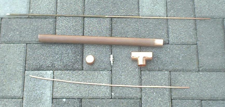
Material
50 cm copper pipe, diameter 28 mm or 1 inch
T-fitting diameter 28 mm or 1 inch
End-fitting diameter 28 mm or 1 inch
Antenna jack N oder BNC
1 m pipe copper or brass, diameter approx. 4 mm
53 cm copper wire 3.7 mm or AWG 7
5 cm copper wire 1.3 mm or AWG 16
The diameters are not critical. You can use the same material for
the radiating rod and the inner conductor of the matching unit lambda/4. The
diameter of the rod and the inner conductor can vary from 3.3 to 4.1
mm, like AWG 6, 7 or 8.
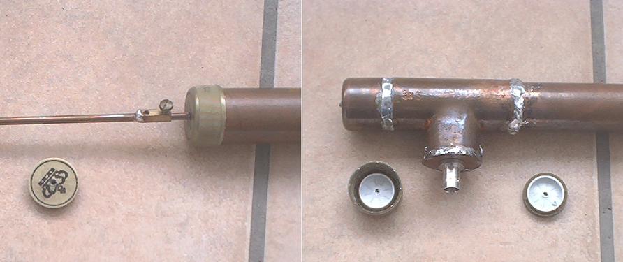
The fittings must be solderable because of the electrical contact. Some newer fittings have a plastic gasket inside.
Drill a hole into the end-fitting. Put the inner conductor in it and solder both.
Bend a loop into the thin wire, the connection between the inner conductor and the antenna jack.
Cut
the copper pipe into two pieces. The lower piece is about 40 mm long.
The upper piece is about 425 mm long. The total length of the matching
unit must be 510 mm. See the 2nd picture. Do not put the pipes fully
into the the fittings. The pipes must be movable some mm for the final
alignment.
Now solder the antenna jack with the inner conductor and
the T-fitting. The distance between the end-fitting and the
connection-wire (loop) to the antenna jack is 65 mm.
Now build a washer for the upper part of the matching unit. It
makes the matching unit waterproof and centers the radiating rod. Use
plastic or FR4 (printed circuit board without copper). I found a matching srew cap of a plastic bottle. The material
must be a good electrical insulator. At 100 Watts the voltage between
the rod and the copper-pipe is about 500 Volts!
Mount the radiating rod. The total length is 980 mm, see the 2nd picture.
Fine tuning
You
have soldered the antenna jack and the inner conductor with the
end-fitting. The fittings are still unsoldered with the two pipes.
Now
connect your transceiver to the antenna. Install a S-meter. Best place
is between the antenna and the coax-cable. The SWR shold be < 2. If
the SWR is very high, you have made a mistake or the electrical
connection between the pipes and the fittings is very bad.
Now move
the upper and lower pipe for best SWR. The SWR shold be lower than 1.5
between 145.000 and 145.500 MHz (German FM-section for simplex and
relais TX).
If the SWR is fine, solder the fittings with the
pipes. Be careful. If you use to much heat while soldering, the antenna
jack or the loop of the connection-wire will loosen...
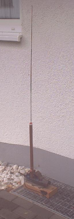
Normally you
test and align the antenna "free space" at least 1 m over ground. The
better choice is, to test and align the anntenna, where it will be
mounted.
After all, use plastic spray for good insulation,
especially between the radiating rod and the upper pipe. The whole
antenna must be waterproof.
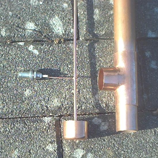
Here
you see the details of the antenna after soldering and mounting the
radiating rod. I used two washers to center the inner conductor inside
the pipe. You can do this too, it is not really necessary.
Here you see the radiation pattern, elevation. Antenna 6 m over ground.
Look at the elevation angle, only 4 degrees!
You can use the antenna in horizontal polarisation, too. The diagram is similar to a dipole, the typical "8".
The elevation angle is similar like the angle in vertical mounting.